Difference between revisions of "JunOS BGP/LAG/OSPF"
| Line 921: | Line 921: | ||
[[file:vrrp6.png]] | [[file:vrrp6.png]] | ||
| + | |||
| + | ===Verification on second switch=== | ||
| + | ppaul2@asw-b1-dfw# run show interfaces terse | match ae | ||
| + | xe-0/1/0.0 up up aenet --> ae1.0 | ||
| + | xe-0/1/1.0 up up aenet --> ae2.0 | ||
| + | ae0 up down | ||
| + | ae1 up up | ||
| + | ae1.0 up up eth-switch | ||
| + | ae2 up up | ||
| + | ae2.0 up up eth-switch | ||
===Checking all=== | ===Checking all=== | ||
Revision as of 23:05, 6 July 2019
In this Tutorial We will be discussing how to setup an External Border Gateway Protocol (EBGP) between two routers.
Prerequisites
To complete this tutorial, you will need:
- A laptop running Linux or MacOS. for this tutorial I will be using a laptop running Ubuntu 16
- A console cable. Since all the new laptops today don't come with a console port, you will need a USB to Console adapter
- The program "Screen"
If you don't have "screen" install it with the command below
sudo apt-get install screen
Goal 1: BGP
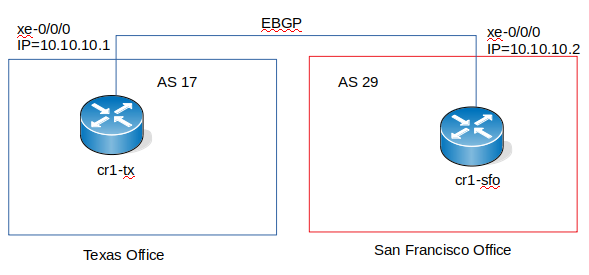
Goal 1 is to setup the network like in the above image.
We have 2 offices. One in Texas and the other one in San Fransisco. Both offices have a Juniper MX80 router. The Texas router cr1-tx is in AS 17 and the San Fransico router cr1-sfo is in AS 29. We need to setup an External Border Gateway Protocol (EBGP) to connect both offices. If we were to connect 2 router in the same AS, we was going to use an IBGP (Internal Border Gateway Protocol) such as OSPF. We will discuss about this in another tutorial.
Router Setup
We are going to perform the basic setup of the router like we did for the switches in [[JunOS Basics[1]]
The process is the same. Please refer to the link above
- Access the router
- Setup the root password
- Setup the device name
- Create a privilege user
- setup Management interface and enable SSH
Note: for the management setup, since we are using a router the management interface on the MX80 is not me0 like on the switch. The management interface is fxp0. See below for the how the management interface is setup.
root@cr1-tx# show interfaces
fxp0 {
    description mgmt;
    unit 0 {
        family inet {
            address 10.192.0.103/24;
        }
    }
}
After setting up all the basic on both routers, it is time to process to the EBGP setup.
EBGP Setup
On cr1-tx
We are going to use the interface xe-0/0/0 which is a 10Gbs interfaces.
Step 1: Set interface description
set interfaces xe-0/0/0 description to-cr1-sfo
- Check before committing
root@cr1-tx# show | compare
[edit interfaces]
+   xe-0/0/0 {
+       description to-cr1-sfo;
+   }
Step 2: Assign an IP address to the interface
set interfaces xe-0/0/0 unit 0 family inet address 10.10.10.1/30
- Check before committing
root@cr1-tx# show | compare
[edit interfaces xe-0/0/0]
+    unit 0 {
+        family inet {
+            address 10.10.10.1/30;
+        }
+    }
Step 3: Set the Autonomous system (AS) number To set the AS number we need to be in the routing-options level for that type in
edit routing-options
[edit routing-options]
root@cr1-tx# set autonomous-system 17
step 4 : Create the BGP group/ add external neighbor address
To do this we need to be in the protocols bgp group external-peers level
Type "exit" to leave the routing-options level and then type in
[edit]
root@cr1-tx# edit protocols bgp group external-peers

[edit protocols bgp group external-peers]
root@cr1-tx# set neighbor 10.10.10.2
Step 5: Specify external AS number
[edit protocols bgp group external-peers]
root@cr1-tx# set peer-as 29
Step 6: Set the peer type
[edit protocols bgp group external-peers]
root@cr1-tx# set type external
Type " exit"
Checking
[edit]
root@cr1-tx# show interfaces
xe-0/0/0 {
    description to-cr1-sfo;
    unit 0 {
        family inet {
            address 10.10.10.1/30;
        }
    }
}
[edit]
root@cr1-tx# show protocols
bgp {
    group external-peers {
        type external;
        peer-as 29;
        neighbor 10.10.10.2;
    }
}
[edit]
root@cr1-tx# show routing-options
autonomous-system 17;
If everything looks good, you can commit
Verification
In operation mode,do show run neighbor
root@cr1-tx> show bgp neighbor
Peer: 10.10.10.2 AS 29         Local: unspecified AS 17
  Type: External    State: Idle           Flags: <PeerInterfaceError>
  Last State: NoState       Last Event: NoEvent
  Last Error: None
  Options: <Preference PeerAS Refresh>
  Holdtime: 90 Preference: 170
  Number of flaps: 0
We can see from the output the Local= unspecified and the state is Idle Last State: NoState Last Event: NoEvent. The reason being that we haven't setup cr1-sfo yet.
On cr1-sfo
We are going to use the interface xe-0/0/0 which is a 10Gbs interfaces.
Step 1: Set interface description
[edit]
root@cr1-sfo# set interfaces xe-0/0/0 description to-cr1-sfo
Step 2: Assign an IP address to the interface
set interfaces xe-0/0/0 unit 0 family inet address 10.10.10.2/30
- Check before committing
root@cr1-sfo# show | compare
[edit interfaces]
+   xe-0/0/0 {
+       description to-cr1-sfo;
+       unit 0 {
+           family inet {
+               address 10.10.10.2/30;
+           }
+       }
+   }
Step 3: Set the Autonomous system (AS) number
To set the AS number we need to be in the routing-options level for that type in
edit routing-options
[edit routing-options]
root@cr1-tx# set autonomous-system 29
step 4 : Create the BGP group/ add external neighbor address
To do this we need to be in the protocols bgp group external-peers level
Type "exit" to leave the routing-options level and then type in
[edit]
root@cr1-tx# edit protocols bgp group external-peers

[edit protocols bgp group external-peers]
root@cr1-tx# set neighbor 10.10.10.1
Step 5: Specify external AS number
[edit protocols bgp group external-peers]
root@cr1-tx# set peer-as 17
Step 6: Set the peer type
[edit protocols bgp group external-peers]
root@cr1-tx# set type external
Type " exit"
Checking
[edit]
root@cr1-sfo# show interfaces
xe-0/0/0 {
    description cr1-sfo;
    unit 0 {
        family inet {
            address 10.10.10.2/30;
        }
    }
}
[edit]
root@cr1-sfo# show protocols
bgp {
    group external-peers {
        type external;
        peer-as 17;
        neighbor 10.10.10.1;
    }
}
[edit]
root@cr1-sfo# show routing-options
autonomous-system 29;
Now that we have cr1-sfo setup let us go back to cr1-tx and run again "show bgp neighbor"
Verification
- On cr1-tx
root@cr1-tx> show bgp neighbor
Peer: 10.10.10.2+55085 AS 29   Local: 10.10.10.1+179 AS 17
 Type: External    State: Established    Flags: <Sync>
 Last State: OpenConfirm   Last Event: RecvKeepAlive
 Last Error: None
 Options: <Preference PeerAS Refresh>
 Holdtime: 90 Preference: 170
 Number of flaps: 0
 Peer ID: 10.10.10.2      Local ID: 10.10.10.1        Active Holdtime: 90
 Keepalive Interval: 30         Group index: 0    Peer index: 0
 BFD: disabled, down
 Local Interface: xe-0/0/0.0
 NLRI for restart configured on peer: inet-unicast
 NLRI advertised by peer: inet-unicast
 NLRI for this session: inet-unicast
 Peer supports Refresh capability (2)
 Stale routes from peer are kept for: 300
 Peer does not support Restarter functionality
 NLRI that restart is negotiated for: inet-unicast
 NLRI of received end-of-rib markers: inet-unicast
 NLRI of all end-of-rib markers sent: inet-unicast
 Peer supports 4 byte AS extension (peer-as 29)
 Peer does not support Addpath
 Table inet.0 Bit: 10000
   RIB State: BGP restart is complete
   Send state: in sync
   Active prefixes:              0
   Received prefixes:            0
   Accepted prefixes:            0
   Suppressed due to damping:    0
   Advertised prefixes:          0
 Last traffic (seconds): Received 10   Sent 6    Checked 65
 Input messages:  Total 5      Updates 1       Refreshes 0     Octets 139
 Output messages: Total 5      Updates 0       Refreshes 0     Octets 158
 Output Queue[0]: 0
- On cr1-sfo
root@cr1-sfo> show bgp neighbor
Peer: 10.10.10.1+179 AS 17     Local: 10.10.10.2+55085 AS 29
 Type: External    State: Established    Flags: <Sync>
 Last State: OpenConfirm   Last Event: RecvKeepAlive
 Last Error: None
 Options: <Preference PeerAS Refresh>
 Holdtime: 90 Preference: 170
 Number of flaps: 0
 Peer ID: 10.10.10.1      Local ID: 10.10.10.2        Active Holdtime: 90
 Keepalive Interval: 30         Group index: 0    Peer index: 0
 BFD: disabled, down
 Local Interface: xe-0/0/0.0
 NLRI for restart configured on peer: inet-unicast
 NLRI advertised by peer: inet-unicast
 NLRI for this session: inet-unicast
 Peer supports Refresh capability (2)
 Stale routes from peer are kept for: 300
 Peer does not support Restarter functionality
 NLRI that restart is negotiated for: inet-unicast
 NLRI of received end-of-rib markers: inet-unicast
 NLRI of all end-of-rib markers sent: inet-unicast
 Peer supports 4 byte AS extension (peer-as 17)
 Peer does not support Addpath
 Table inet.0 Bit: 10000
   RIB State: BGP restart is complete
   Send state: in sync
   Active prefixes:              0
   Received prefixes:            0
   Accepted prefixes:            0
   Suppressed due to damping:    0
   Advertised prefixes:          0
 Last traffic (seconds): Received 2    Sent 18   Checked 23
 Input messages:  Total 15     Updates 1       Refreshes 0     Octets 289
 Output messages: Total 16     Updates 0       Refreshes 0     Octets 367
 Output Queue[0]: 0
We have setup peering between cr1-tx and cr1-sfo.
BGP verification commands
show bgp neighbor

show bgp group

show bgp summary
Goal 2: LAG
Link aggregation enables you to group interfaces to form a single link layer interface; also knows as a LAG (Link Aggregation Group).
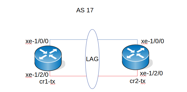
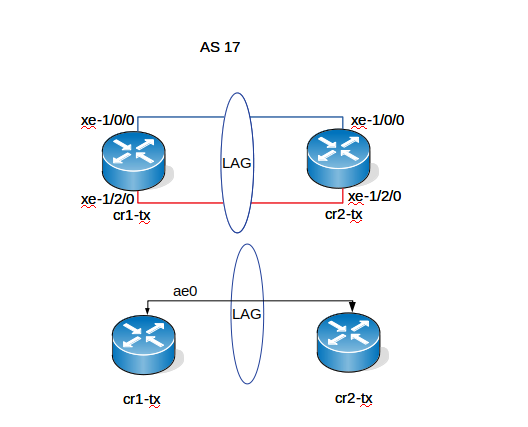
In goal 2, we are going to setup Link Aggregation group (LAG) with Link Aggregation Control Protocol (LACP) between cr1 and cr2 using interfaces xe-1/0/0 and xe-1/2/0 on both routers.
This needs to be done on both routers
On cr1
- Step 1: Create the aggregation Ethernet Interface(s)
In "Edit" or "configuration mode", run:
set chassis aggregated-devices ethernet device-count 1
This will create 1 aggregated ethernet interface (ae0) because of the number 1 after device-count. If device-count was = 3, this will create 3 ae's (ae0, ae1 and ae3). commit the changes
[edit]
root@cr1-tx# run show interfaces terse | match ae
ae0                     up    down
- Step 2: Specify the number of interfaces
edit]
root@cr1-tx# set interfaces xe-1/0/0  gigether-options 802.3ad ae0
root@cr1-tx# set interfaces xe-1/2/0  gigether-options 802.3ad ae0
Note: If you was using a 1G interface, replace gigether-options with ether-options
- Step 3: Specify an interface family and interface properties
root@cr1-tx# set interfaces ae0 unit 0 family inet address 10.192.0.105/24
root@cr1-tx# set interfaces ae0 aggregated-ether-options lacp active
commit and verify.
[edit]
root@cr1-tx# run show interfaces terse | match ae
xe-1/0/0.0              up    up   aenet    --> ae0.0
xe-1/2/0.0              up    up   aenet    --> ae0.0
ae0                     up    down
ae0.0                   up    down inet     192.168.0.1/30
We see both ae0 and ae0.0 are showing down. This is because we haven't configured cr2 yet.
On cr2
Perform the same steps on cr2 and change the IP address to 10.192.0.106. Below is the configuration of cr2 before commit
root@cr2-tx# show | compare
[edit interfaces]
+   xe-1/0/0 {
+       gigether-options {
+           802.3ad ae0;
+       }
+   }
+   xe-1/2/0 {
+       gigether-options {
+           802.3ad ae0;
+       }
+   }
+   ae0 {
+       aggregated-ether-options {
+           lacp {
+               active;
+           }
+       }
+       unit 0 {
+           family inet {
+               address 192.168.0.2/30;
+           }
+       }
+   }
Verification
[edit]
root@cr1-tx# run show interfaces terse | match ae
xe-1/0/0.0              up    up   aenet    --> ae0.0
xe-1/2/0.0              up    up   aenet    --> ae0.0
ae0                     up    up
ae0.0                   up    up   inet     192.168.0.1/30
[edit]
root@cr2-tx# run show interfaces terse | match ae
xe-1/0/0.0              up    up   aenet    --> ae0.0
xe-1/2/0.0              up    up   aenet    --> ae0.0
ae0                     up    up
ae0.0                   up    up   inet     192.168.0.2/30
Testing
From cr1-tx ping 192.168.0.2
root@cr1-tx> ping 192.168.0.2
PING 192.168.0.2 (192.168.0.2): 56 data bytes
64 bytes from 192.168.0.2: icmp_seq=0 ttl=64 time=0.832 ms
64 bytes from 192.168.0.2: icmp_seq=1 ttl=64 time=0.759 ms
64 bytes from 192.168.0.2: icmp_seq=2 ttl=64 time=0.758 ms
From cr2-tx ping 192.168.0.1
root@cr2-tx> ping 192.168.0.1
PING 192.168.0.1 (192.168.0.1): 56 data bytes
64 bytes from 192.168.0.1: icmp_seq=0 ttl=64 time=0.779 ms
64 bytes from 192.168.0.1: icmp_seq=1 ttl=64 time=0.704 ms
64 bytes from 192.168.0.1: icmp_seq=2 ttl=64 time=16.159 ms
Goal 3: OSPF
In goal 2 we used 2 interfaces on each router to set a LAG (ae0). In Goal 3 we are going to setup OSPF on the ae0 interface on both router. the command is :
root@cr1-tx# set protocols ospf area 0.0.0.0 interface ae0
Verification
- on cr1-tx
root@cr1-tx> show ospf neighbor
Address          Interface              State     ID               Pri  Dead
192.168.0.2      ae0.0                  Full      10.10.10.2       128    35
root@cr1-tx> show ospf interface
Interface           State   Area            DR ID           BDR ID          Nbrs
ae0.0               DR      0.0.0.0         10.10.10.1      10.10.10.2         1
root@cr1-tx> show ospf route
Topology default Route Table:
Prefix             Path  Route      NH       Metric NextHop       Nexthop
                   Type  Type       Type            Interface     Address/LSP
10.10.10.2         Intra Router     IP            1 ae0.0         192.168.0.2
192.168.0.0/30     Intra Network    IP            1 ae0.0
root@cr1-tx> show ospf database
 OSPF database, Area 0.0.0.0
Type       ID               Adv Rtr           Seq      Age  Opt  Cksum  Len
Router  *10.10.10.1       10.10.10.1       0x80000004   533  0x22 0x4ece  36
Router   10.10.10.2       10.10.10.2       0x80000002   534  0x22 0x50cb  36
Network *192.168.0.1      10.10.10.1       0x80000001   538  0x22 0x5b19  32
- on cr2-tx
root@cr2-tx# run show ospf neighbor
Address          Interface              State     ID               Pri  Dead
192.168.0.1      ae0.0                  Full      10.10.10.1       128    36
root@cr2-tx> show ospf interface
Interface           State   Area            DR ID           BDR ID          Nbrs
ae0.0               BDR     0.0.0.0         10.10.10.1      10.10.10.2         1
Goal 4: VRRP
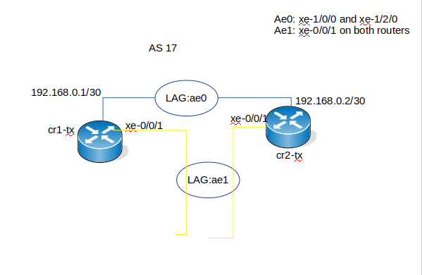
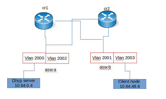
The goal as we can see in the image above is to setup VRRP on two ae interfaces on both routers that are going to connect 4 different VLAN's on two differents switches
| Devices | interface | Members | IP address | Virtual IP | VRRP group | VAN-id |
| cr1 | ae1 | xe-0/0/1 | 10.64.0.2 | 10.64.0.1 | 17 | 2000 |
| cr2 | ae1 | xe-0/0/1 | 10.64.0.3 | 10.64.0.1 | 17 | 2000 |
| cr1 | ae1 | xe-0/0/1 | 10.64.32.2 | 10.64.32.1 | 2 | 2002 |
| cr2 | ae1 | xe-0/0/1 | 10.64.32.3 | 10.64.32.1 | 2 | 2002 |
| cr1 | ae2 | xe-0/0/2 | 10.64.16.2 | 10.64.16.1 | 1 | 2001 |
| cr2 | ae2 | xe-0/0/2 | 10.64.16.3 | 10.64.16.1 | 1 | 2001 |
| cr1 | ae2 | xe-0/0/2 | 10.64.48.2 | 10.64.48.1 | 3 | 2003 |
| cr2 | ae2 | xe-0/0/2 | 10.64.48.3 | 10.64.48.1 | 3 | 2003 |
| Devices | interface | members | VLAN | VLAN-id |
| asw-a | ae1 | xe-0/1/0 | private1-a | 2000 |
| asw-a | ae2 | xe-0/1/2 | private1-c | 2002 |
| asw-b | ae1 | xe-0/1/0 | private1-b | 2001 |
| asw-b | ae2 | xe-0/1/2 | private1-d | 2003 |
To accomplish this goal, we are going to break it in different steps
Step 1 : Setup ae1 interfaces on both routers and configure VRRP
ae1 setup
Run all the commands on both routers.
To setup LAG in Goal2 we use the command
set chassis aggregated-devices ethernet device-count 1
Which did create one ae interface (ae0). Since we need 2 more ae interfaces (ae1 and ae2) we are going to use the same command but change the 1 to 3
set chassis aggregated-devices ethernet device-count 3
For now we are not going to touch ae2, we will work only on ae1
Assign a member to ae1
set interfaces xe-0/0/1 gigether-options 802.3ad ae1
set interfaces xe-0/0/1 description "core:asw-a1-dfw:xe-0/1/0"
configure the ae1 interfaces
set interfaces ae1 description "Core: asw-a-dfw:xe-0/1/0"
set interfaces ae1 aggregated-ether-options lacp active
set interfaces ae1 aggregated-ether-options lacp periodic fast
set interfaces ae1 encapsulation flexible-ethernet-services
set interfaces ae1 mtu 9192
set interfaces ae1 flexible-vlan-tagging
VRRP setup
- For the private-a-dfw vlan
set interfaces ae1 unit 2000 family inet address 10.64.0.2/22
set interfaces ae1 unit 2000 description "Subenet private-a-dfw"
set interfaces ae1 unit 2000 vlan-id 2000
set interfaces ae1 unit 2000 family inet address 10.64.0.2/22 vrrp-group 17 virtual-address 10.64.0.1
set interfaces ae1 unit 2000 family inet address 10.64.0.2/22 vrrp-group 17 track interface ae1.2000 bandwidth-threshold 5g priority-cost 50
set interfaces ae1 unit 2000 family inet address 10.64.0.2/22 vrrp-group 17 track interface ae1.2000 bandwidth-threshold 8g priority-cost 30
- For the private-c-dfw vlan
set interfaces ae1 unit 2002 family inet address 10.64.32.2/22
set interfaces ae1 unit 2002 description "Subenet private-c-dfw"
set interfaces ae1 unit 2002 vlan-id 2002
set interfaces ae1 unit 2002 family inet address 10.64.32.2/22 vrrp-group 2 virtual-address 10.64.32.1
set interfaces ae1 unit 2002 family inet address 10.64.32.2/22 vrrp-group 2 track interface ae1.2002 bandwidth-threshold 5g priority-cost 50
set interfaces ae1 unit 2002 family inet address 10.64.32.2/22 vrrp-group 2 track interface ae1.2002 bandwidth-threshold 8g priority-cost 30
Verification
- On cr1
root@cr1-tx# show interfaces ae1
description "Core: asw-a-dfw";
flexible-vlan-tagging;
mtu 9192;
encapsulation flexible-ethernet-services;
aggregated-ether-options {
   lacp {
       active;
       periodic fast;
   }
}
unit 2000 {
   description "Subnet private1-a-dfw";
   vlan-id 2000;
   family inet {
       address 10.64.0.2/22 {
           vrrp-group 17 {
               virtual-address 10.64.0.1;
               track {
                   interface ae1.2000 {
                       bandwidth-threshold 5g priority-cost 50;
                       bandwidth-threshold 8g priority-cost 30;
                   }
               }
           }
       }
   }
}
unit 2002 {
   description " Subnet private-c-dfw";
   vlan-id 2002;
   family inet {
       address 10.64.32.2/22 {
           vrrp-group 2 {
               virtual-address 10.64.32.1;
               track {
                   interface ae1.2002 {
                       bandwidth-threshold 5g priority-cost 50;
                       bandwidth-threshold 8g priority-cost 30;
                   }
               }
           }
       }
   }
- On cr2
root@cr2-tx# show interfaces ae1
description "Core: asw-a1-dfw";
flexible-vlan-tagging;
mtu 9192;
encapsulation flexible-ethernet-services;
aggregated-ether-options {
   lacp {
       active;
       periodic fast;
   }
}
unit 2000 {
   description "Subnet private1-a-dfw";
   vlan-id 2000;
   family inet {
       address 10.64.0.3/22 {
           vrrp-group 17 {
               virtual-address 10.64.0.1;
               track {
                   interface ae1.2000 {
                       bandwidth-threshold 5g priority-cost 50;
                       bandwidth-threshold 8g priority-cost 30;
                   }
               }
           }
       }
   }
}
unit 2002 {
   description "Subnet private1-c-dfw";
   vlan-id 2002;
   family inet {
       address 10.64.32.3/22 {
           vrrp-group 2 {
               virtual-address 10.64.32.1;
               track {
                   interface ae1.2003 {
                       bandwidth-threshold 5g priority-cost 50;
                       bandwidth-threshold 8g priority-cost 30;
                   }
               }
           }
       }
   }
}
Testing
root@cr1-tx# run show vrrp
Interface     State       Group   VR state VR Mode   Timer    Type   Address
ae1.2000      down           17   init     Active      N  0.000 lcl   10.64.0.2
                                                               vip    10.64.0.1
ae1.2002      down            2   init     Active      N  0.000 lcl   10.64.32.2
                                                               vip    10.64.32.1
root@cr2-tx# run show vrrp
Interface     State       Group   VR state VR Mode   Timer    Type   Address
ae1.2000      down           17   init     Active      N  0.000 lcl   10.64.0.3
                                                               vip    10.64.0.1
ae1.2002      down            2   init     Active      N  0.000 lcl   10.64.32.3
                                                               vip    10.64.32.1
We going to connect cr1:xe-0/0/1 to cr2:xe-0/0/1 to make sure that ae1 is up and vrrp is working for now before we move both interfaces to the switch
root@cr1-tx# run show interfaces terse | match ae1
xe-0/0/1.2000           up    up   aenet    --> ae1.2000
xe-0/0/1.2002           up    up   aenet    --> ae1.2002
xe-0/0/1.32767          up    up   aenet    --> ae1.32767
ae1                     up    up
ae1.2000                up    up   inet     10.64.0.2/22
ae1.2002                up    up   inet     10.64.32.2/22
ae1.32767               up    up   multiservice

root@cr2-tx# run show interfaces terse | match ae1
xe-0/0/1.2000           up    up   aenet    --> ae1.2000
xe-0/0/1.2002           up    up   aenet    --> ae1.2002
xe-0/0/1.32767          up    up   aenet    --> ae1.32767
ae1                     up    up
ae1.2000                up    up   inet     10.64.0.3/22
ae1.2002                up    up   inet     10.64.32.3/22
ae1.32767               up    up   multiservice
root@cr1-tx# run show vrrp
Interface     State       Group   VR state VR Mode   Timer    Type   Address
ae1.2000      up             17   backup   Active      D  3.423 lcl    10.64.0.2
                                                               vip    10.64.0.1
                                                               mas    10.64.0.3
ae1.2002      up              2   master   Active      A  0.630 lcl    10.64.32.2
                                                              vip    10.64.32.1
root@cr2-tx# run show vrrp
Interface     State       Group   VR state VR Mode   Timer    Type   Address
ae1.2000      up             17   master   Active      A  0.607 lcl    10.64.0.3
                                                               vip    10.64.0.1
ae1.2002      up              2   backup   Active      D  3.278 lcl    10.64.32.3
                                                               vip    10.64.32.1
                                                               mas    10.64.32.2
Step 2 : Set up the switch
We are going to setup ae1 and ae2 on asw-a-dfw and assign xe-0/1/0 to ae1 and xe-0/1/2 to ae2. After that we assign ae1 and ae2 to private1-a and private1-c.
Since we have already setup all the VLAN's on the switch ( see JunOS Baics) we are just going to work on the ae links
create the ae interfaces
set chassis aggregated-devices ethernet device-count 3
We are going to use only ae1 and ae2 for now and leave ae0 assign member(s) to ae1 ad ae2
set interfaces xe-0/1/0 ethernet-options 802.3ad ae1
set interfaces xe-0/1/2 ethernet-options 802.3ad ae2
configure ae1 and ae2
set interfaces ae1 description "Core:cr1:ae1"
set interfaces ae1 aggregated-ether-options lacp active periodic fast
set interfaces ae1 unit 0 family ethernet-switching port-mode trunk
set interfaces ae1 unit 0 family ethernet-switching vlan members private1-a-dfw
set interfaces ae1 unit 0 family ethernet-switching vlan members private1-c-dfw
set interfaces ae2 description "Core: <<cr2:ae1"
set interfaces ae2 aggregated-ether-options lacp active periodic fast
set interfaces ae2 unit 0 family ethernet-switching port-mode trunk
set interfaces ae2 unit 0 family ethernet-switching vlan members private1-a-dfw
set interfaces ae2 unit 0 family ethernet-switching vlan members private1-c-dfw
Verification
ppaul2@asw-a1-dfw# show interfaces ae1
description "Core: <<cr1:ae1";
aggregated-ether-options {
   lacp {
       active;
       periodic fast;
   }
}
unit 0 {
   family ethernet-switching {
       port-mode trunk;
       vlan {
           members [ private1-a-dfw private1-c-dfw ];
       }
   }
}
ppaul2@asw-a1-dfw# run show interfaces terse | match ae
xe-0/1/0.0              up    down aenet    --> ae1.0
xe-0/1/2.0              up    down aenet    --> ae2.0
ae0                     down  down
ae1                     up    down
ae1.0                   up    down eth-switch
ae2                     up    down
ae2.0                   up    down eth-switch
We are not using ae0 so we have it set to disable. for ae1 and ae2 we are seeing it is show down. The reason being we still have cr1:xe-0/0/1 and cr2:xe-0/0/1 connected together.
We need to move cr1:xe-0/0/1 to asw-a:xe-0/1/0 and cr2:xe0/0/0 to asw-a:xe-0/1/2.
Test
After moving the connections
ppaul2@asw-a1-dfw# run show interfaces terse | match ae
xe-0/1/0.0              up    up   aenet    --> ae1.0
xe-0/1/2.0              up    up   aenet    --> ae2.0
ae0                     down  down
ae1                     up    up
ae1.0                   up    up   eth-switch
ae2                     up    up
ae2.0                   up    up   eth-switch
- on cr1
root@cr1-tx> show vrrp
Interface     State       Group   VR state VR Mode   Timer    Type   Address
ae1.2000      up             17   backup   Active      D  3.271 lcl    10.64.0.2
                                                               vip    10.64.0.1
                                                               mas    10.64.0.3
ae1.2002      up              2   master   Active      A  0.519 lcl    10.64.32.2
                                                               vip    10.64.32.1
- On cr2
root@cr2-tx> show vrrp
Interface     State       Group   VR state VR Mode   Timer    Type   Address
ae1.2000      up             17   master   Active      A  0.249 lcl    10.64.0.3
                                                               vip    10.64.0.1
ae1.2002      up              2   backup   Active      D  2.735 lcl    10.64.32.3
                                                               vip    10.64.32.1
                                                               mas    10.64.32.2
Commands
root@cr1-tx> show vrrp track
Track Int   State         Speed   VRRP Int   Group   VR State      Current prio
ae1.2000    up              10g   ae1.2000      17   backup                 100
ae1.2002    up              10g   ae1.2002       2   backup                 100
root@cr2-tx> show vrrp track
Track Int   State         Speed   VRRP Int   Group   VR State      Current prio
ae1.2000    up              10g   ae1.2000      17   master                 100
ae1.2002    up              10g   ae1.2002       2   master                 100
show vrrp summary
show vrrp interface ae
Note
You can setup authentication method if you want to have authentication for VRRP. The command to do that will be:
set interfaces ae1 unit 2000 family inet address 10.64.0.2 vrrp-group 17 authentication-type md5
set interfaces ae1 unit 2000 family inet address 10.64.0.2 vrrp-group 17 authentication-key yourpassword
set interfaces ae1 unit 2002 family inet address 10.64.32.2 vrrp-group 2 authentication-type md5
set interfaces ae1 unit 2002 family inet address 10.64.32.2 vrrp-group 2 authentication-key yourpassword
The password needs to be the same on both routers.
Setp3: setup ae2 and second switch
To setup ae2, follow Step1: Setup ae1 interfaces on both routers and configure VRRP. just replace ae1 with ae2
For VRRP, see information below
| Unit | address cr1 | address cr2 | vlan-id | vrrp group | virtual address |
| 2001 | 10.64.16.2 | 10.64.16.3 | 2001 | 1 | 10.64.16.1 |
| 2003 | 10.64.48.2 | 10.64.48.3 | 2003 | 3 | 10.64.48.1 |
Verrification
Like we did with ae1, we are going to connect cr1:xe-0/0/2 to cr2:xe-0/0/2 to make sure that ae2 is up and vrrp is working for now before we move both interfaces to the switch (asw-b)
- On cr1
root@cr1-tx> show interfaces terse | match ae
xe-0/0/1.2000           up    up   aenet    --> ae1.2000
xe-0/0/1.2002           up    up   aenet    --> ae1.2002
xe-0/0/1.32767          up    up   aenet    --> ae1.32767
xe-0/0/2.2001           up    up   aenet    --> ae2.2001
xe-0/0/2.2003           up    up   aenet    --> ae2.2003
xe-0/0/2.32767          up    up   aenet    --> ae2.32767
xe-1/0/0.0              up    up   aenet    --> ae0.0
xe-1/2/0.0              up    up   aenet    --> ae0.0
ae0                     up    up
ae0.0                   up    up   inet     192.168.0.1/30
ae1                     up    up
ae1.2000                up    up   inet     10.64.0.2/22
ae1.2002                up    up   inet     10.64.32.2/22
ae1.32767               up    up   multiservice
ae2                     up    up
ae2.2001                up    up   inet     10.64.16.2/22
ae2.2003                up    up   inet     10.64.48.2/22
ae2.32767               up    up   multiservice
- On cr2
root@cr2-tx# run show interfaces terse | match ae
xe-0/0/1.2000           up    up   aenet    --> ae1.2000
xe-0/0/1.2002           up    up   aenet    --> ae1.2002
xe-0/0/1.32767          up    up   aenet    --> ae1.32767
xe-0/0/2.2001           up    up   aenet    --> ae2.2001
xe-0/0/2.2003           up    up   aenet    --> ae2.2003
xe-0/0/2.32767          up    up   aenet    --> ae2.32767
xe-1/0/0.0              up    up   aenet    --> ae0.0
xe-1/2/0.0              up    up   aenet    --> ae0.0
ae0                     up    up
ae0.0                   up    up   inet     192.168.0.2/30
ae1                     up    up
ae1.2000                up    up   inet     10.64.0.3/22
ae1.2002                up    up   inet     10.64.32.3/22
ae1.32767               up    up   multiservice
ae2                     up    up
ae2.2001                up    up   inet     10.64.16.3/22
ae2.2003                up    up   inet     10.64.48.3/22
ae2.32767               up    up   multiservice
We can see that ae2.2001 and ae2.2003 are up on both routers.
For the second switch configuration, this will be the same as the first switch configuration.
The only difference we will have vlan private1-b-dfw and private1-d-dfw
Verification on second switch
ppaul2@asw-b1-dfw# run show interfaces terse | match ae
xe-0/1/0.0              up    up   aenet    --> ae1.0
xe-0/1/1.0              up    up   aenet    --> ae2.0
ae0                     up    down
ae1                     up    up
ae1.0                   up    up   eth-switch
ae2                     up    up
ae2.0                   up    up   eth-switch
Checking all
- On cr1
- on cr2
Scenario 1: DHCP server
As we can see in the above image, Our DHCP server is in private1-a-dfw VLAN with VLAN_ID 2000 and we have client host in private1-d-dfw VLAN with VLAN_ID 2003.
The client host will not be able to talk to the DHCP server since both DHCP server and client hosts are in different VLAN's. To resolve this problem we need to setup on both routers cr1 and cr2 a helper. The command to do that will b;
set forwarding-options helpers bootp server 10.64.0.4
10.64.04 being the DHCP server IP address. Then
set forwarding-options helpers bootp interface ae1.2000
set forwarding-options helpers bootp interface ae2.2001
set forwarding-options helpers bootp interface ae1.2002
set forwarding-options helpers bootp interface ae2.2003
- Verification
In edit mode do:
show forwarding-options
root@cr1-sfo# show forwarding-options
helpers {
    bootp {
        server 10.64.0.4;
        interface {
            ae1.2000;
            ae1.2002;
            ae2.2001;
            ae2.2003;
        }
    }
}
